Rigid-flex boards offer the advantages of rigid printed circuit boards and flexible circuits, producing compact, lightweight assemblies in medical devices, aerospace, automobiles, and wearable technology. In the case you are researching the topic of rigid flex PCB manufacturing, this article walks through the manufacturing procedure, the materials involved, and the quality features you should be aware of, based on practical experience working with contract manufacturers and design engineers.
Rigid-Flex: Difference Between Materials and Purpose
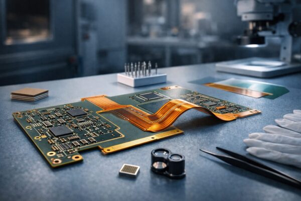
Rigid-flex PCBs incorporate both rigid and flexible substrates bonded together. The flexible areas typically consist of thin polyimide films with copper foils, while the rigid sections are usually based on FR-4 or high-Tg laminates. The flex sections are protected with coverlays, and mechanical support for mounted components is provided through stiffeners. The result is a single-board solution that replaces multiple cable-and-board assemblies, improving reliability while saving space.
Overview of the Rigid-Flex PCB Manufacturing Process
The process of manufacturing rigid-flex PCBs is complex and requires careful coordination between design and fabrication.
DFM and Stackup Decisions
DFM and stackup decisions are made early in the process. In CAD, good production begins with designers defining exact stackups that clearly indicate rigid and flex layers, bending radii, and via styles. Choices such as adhesive versus adhesive-less flex, controlled impedance requirements, microvias, and material selection affect both cost and yield. Designs that include clear DFM notes and realistic bend radii typically move through fabrication more smoothly and reach production faster.
Inner Layer Imaging and Etching
Inner layers are patterned using photolithography for both rigid and flex cores. Signal layers are imaged, chemically etched, and electrically checked for continuity. In multilayer rigid-flex assemblies, inner flex layers are kept thin and tightly controlled to prevent stress and cracking at fold points.
Lamination and Bonding
Multiple cores and prepregs are stacked and laminated under controlled heat and pressure. One key decision at this stage is whether to use adhesive bonding or adhesive-less copper treatment when bonding flex to rigid sections. Adhesive-less constructions reduce the risk of long-term delamination but generally increase cost. Proper lamination is critical to prevent voids and ensure planarity, which is essential for later surface-mount assembly.
Drilling, Plating, and Via Formation
After lamination, through-holes and vias are created using controlled drilling processes. In flex regions, hole quality is especially important to avoid cracking. Copper plating is applied to form reliable plated through-hole connections between layers. High-density rigid areas often incorporate blind and buried vias to support complex routing requirements.
Surface Preparation and Soldermask or Coverlay Application
Rigid regions typically receive soldermask, while flexible areas are protected with polyimide coverlays. Coverlay application requires precise registration and controlled curing to avoid overstressing the flex material. Component mounting areas may include pockets with stiffeners, commonly FR-4 or copper, to support parts without interfering with required flex zones.
Surface Finish and Component Assembly
Common surface finishes include ENIG, lead-free HASL, and immersion silver, selected based on reliability, application, and cost requirements. Once the surface finish is complete, boards proceed to surface-mount assembly as needed. Manufacturers with integrated assembly capabilities can optimize reflow profiles to accommodate the mixed thermal mass of rigid-flex designs.
Inspection, Testing, and Reliability Verification
Electrical testing includes continuity and shorts checks using flying probe or bed-of-nails methods. Automated optical inspection and X-ray inspection are used to detect defects in assemblies and solder joints. Long-term reliability is validated through thermal cycling, bend-fatigue testing, and inspections aligned with industry acceptance criteria.
Selecting a Rigid-Flex PCB Manufacturer
Choosing an experienced rigid-flex PCB manufacturer is essential. Look for suppliers with documented experience, strong DFM support, and proven process control for polyimide materials. Turnkey manufacturers with rapid prototyping capabilities often provide valuable stackup guidance and assembly services that help transition designs smoothly into production. It is important to ask about bend-test data, adhesion testing, and quality certifications.
Some key questions to ask potential suppliers include how flex thickness tolerances are managed, which surface finishes and coverlays are recommended, and whether the manufacturer supports impedance control and advanced bonding techniques for fine-pitch components.
Conclusion: Balancing Cost, Complexity, and Reliability
Rigid-flex PCB manufacturing enables significant design freedom and system-level reliability, but it demands close coordination between design and fabrication. Clearly defined bend specifications, early DFM involvement, and collaboration with an experienced manufacturing partner such as FastTurn PCB can reduce scrap, shorten timelines, and improve overall product quality. Projects that invest engineering effort upfront to specify stackups and bending zones consistently reach the market faster and with fewer unexpected issues.
FAQs
Which is the average lead time for prototypes and production of rigid-flex PCBs?
Lead times depend on design complexity. Simple two- or three-layer rigid-flex prototypes can often be delivered within one to two weeks, while multilayer, high-density designs require longer lamination and testing cycles. Realistic schedules should be discussed early with the fabricator.
What is the effect of flex fatigue on product lifetime, and how is it tested?
Flex fatigue depends on bend radius, number of cycles, and stress concentration points. Manufacturers simulate product lifetime through repeated bend and thermal cycling tests to establish quantified cycle ratings and expected durability.
Is it possible to repair or rework rigid-flex boards if a trace is broken?
Repairs in rigid sections are generally straightforward, while flex repairs are more delicate and require specialized adhesives and coverlay patches. If field repair is anticipated, reworkability should be considered during the design phase.
Are rigid-flex boards more expensive than standard rigid PCBs?
Rigid-flex boards typically cost more due to material and process complexity. However, system-level savings often offset this by eliminating connectors and cables while improving overall reliability.
What design practices improve manufacturability of rigid-flex PCBs?
Conservative bend radii, avoiding vias in flex transition zones, limiting continuous copper across bends, and clearly specifying stiffeners and coverlays all contribute to better manufacturability and long-term reliability.